# Assembling a DIY oscilloscope
I found an interesting DIY oscilloscope on the internet. Basically you get a PCB, some passive components, a small TFT display and connectors. Assemble everything and simply power it on. Assuming you soldered everything properly, no shorts or open ports, you should have a really cheap (less than $20) oscilloscope. Mind you, it's nowhere as good or useful as the professional (and much more expensive) ones, but it can be a nice tool to play with.
In this post I'm simply gonna show you the soldering progress. More thoughts about the finalized product after I get some time to actually do some tests.
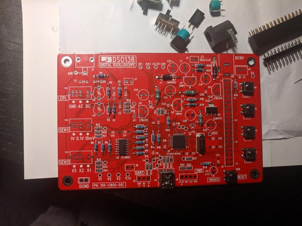
That's how it started
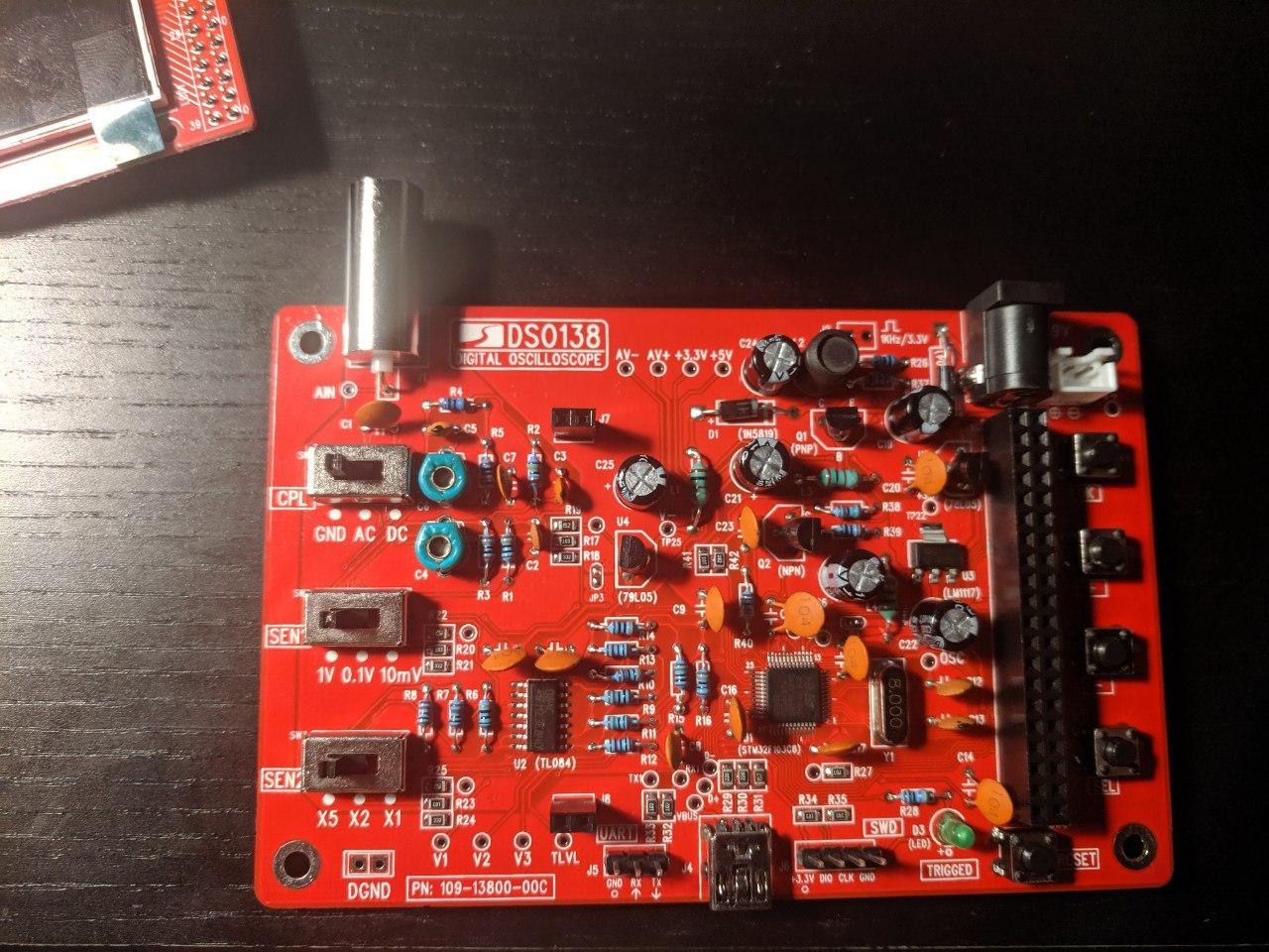
and after soldering everything
Then it was time to check all the voltages on the board, and surprisingly enough, they all checked out. So I placed the display and unfortunately (yes Merphy, I know you're out there, always watching) it wasn't turning on at all. Checked all the voltages again, re-soldered some headers and suddenly it's alive!
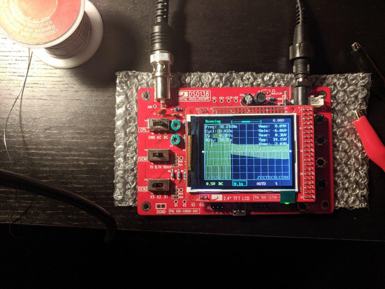
So yeah.. it is working. Testing time now, but more on that, with another post 😃